 Transducers Transducers
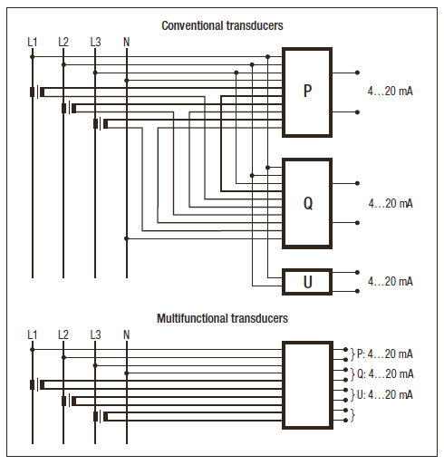
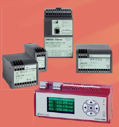
The properties of multifunctional heavy current transducers can be completely programmed.They measure any variable of an electric network. The application (network configuration) and thebehaviour of the analogue and digital outputs can be set by PC software without hardware variants.Measured value acquisition during operation is also supported via the programming or bus interface(Modbus, Profibus, Ethernet or LON). Programmable transducers are more resistant to interference incomparison with indicators and designed for more dynamic behaviour of the input signals.
Unifunctional transducers are of an analogue design. They are customised to the required measuringtask during the manufacturing process. The DC signal proportionate to the measured value can beused for visualising via analogue indicators or further PLC processing. Converters are available for allbasic variables in the electric network
Application
The transducers for alternating current of the P-line are typically connected via current transformers,but can also be used for direct measurement. The measurement is effected within the instrument viacurrent transformers which ensure galvanic isolation. The instruments are designed for sinusoidalalternating current signals. Possibly existing direct current portions are not concurrently measured.
They provide an output signal in form of a direct current signal which is proportional to the measuredcurrent.
The transducers for alternating voltage of the P-line may be connected via voltage transformers,but can also be used for direct measurement. They have been designed for the measurement ofsinusoidal alternating voltage signals. Possibly existing direct voltage portions are not concurrentlymeasured. They provide an output signal in form of a direct current signal which is proportional to themeasured voltage level.
Instruments with live-zero signal can be used for improved failure recognition. If only certain areas ofthe whole measuring range are of interest, U554 with main value magnification or step point.
 The transducers for active or reactive power may be connected via current and voltage transformers,but can also be used for direct measurement. They provide an output signal in form of a directcurrent signal which is proportional to the measured power. Depending on the application, versionsfor measurement in single-phase or three-phase systems with balanced or unbalanced loads areavailable. The transducers for active or reactive power may be connected via current and voltage transformers,but can also be used for direct measurement. They provide an output signal in form of a directcurrent signal which is proportional to the measured power. Depending on the application, versionsfor measurement in single-phase or three-phase systems with balanced or unbalanced loads areavailable.
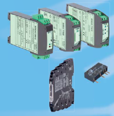
The instruments can be easily snapped onto a top-hat rail (35 x 15 mm or 35 x 7.5 mm).
Multifunctional transducers can be connectedvia current and voltage transformers or directly.All Camille Bauer lines can be used universally.The application (system configuration) as well asnominal values of current and voltage are freelyprogrammable without any hardware variants.The allocation of measured variables to theoutputs and the determination of the limits of themeasuring ranges is also realised using the respective PC software which is made availablefree of charge by us. Service functionssupport users during commissioning. In thisway, e.g. values of analogue or digital outputscan be simulated to test subsequent circuitswithout the measurement input having to beconnected or activated.Instrument variants with a bus connectionprovide all acquired measured values via thecorresponding digital interface.
Overview of the instrument families
|
|
|
|
| Measuring system |
|
|
|
| Sampling values per system period |
24 |
32 |
128 (continuously) |
| Accuracy class |
0.5 |
Analogue outputs: 0.25
Measured variables of bus: 0.2 |
Basic instrument: 0.2
I/O modules: 0.1 |
| Setting time (at 50 Hz) |
≥ 1.0s, depending on the system configuration and the selected measured variables |
≥ 0.3s, depending on the system
configuration and the selected
measured variables |
≥ 0.06s |
| Nominal frequency |
50/60 Hz |
16.7 Hz, 50/60 Hz |
45…65 Hz, 10…70 Hz, 10…140 Hz |
| Nominal current |
1…6 A |
1…6 A |
1…5 A, Overriding up to 10 A |
| Nominal voltage |
57.7…400 V (Ph – N)
100…693 V (Ph – Ph) |
57.7…400 V (Ph – N)
100…693 V (Ph – Ph) |
57…400 V (Ph – N)
100..693 V (P – P) |
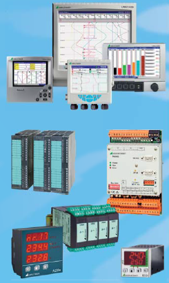
 Display units Display units
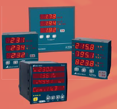
Multifunctional display units are used to monitor energy consumption in distribution facilities. Theycan replace numerous analogue indicators, have an integrated energy counter and partly networkanalysis functions. They may be connected to a PLC or control system via I/Os or bus connections(Modbus, Profibus, Ethernet, LON). Network configuration and connection parameters can beconveniently set via buttons or via PC software. Some versions permit customised parameterizingof display data, e.g. the suppression of displays, priority displays or changing displays with intervalcontrol.
Application
The instruments are designed for measurements in electrical distribution system or industrial plants.All parameters may be set via the display. Configuration can also be performed using A200plussoftware if an EMMOD201 (Modbus) or EMMOD203 (Ethernet) extension module has beentemporarily or permanently plugged into the basic device.
The digital outputs cannot only be used to drive external counters but also for alarming in case oflimit violations. If, for example, the measured variable of current is tested for exceeding a limit value,the same is triggered as soon as at least one of the phase currents exceed the limit value. A limitvalue on the neutral wire helps to minimise the risk that an undersized neutral wire causes insulationdamage or even fires. An extension module may be plugged in to connect supervisory systems or tonetwork devices via Modbus, Profibus, LON or Ethernet.
For mobile use, A210 is also available in a handheld version. A210-HH with data logger is providedin a case including voltage measuring cables, software, battery and system adaptor. Also clip-oncurrent transformers are available, if required.
| |
|
|
|
|
|
Display unit + optional extension module
|
„All in one“
|
| Measuring system |
|
|
|
|
| Voltage, current |
±0.5 % |
±0.2 % |
±0.25 % |
±0.1 % |
| Apparent, active, reactive power |
±1 % |
±0.5 % |
±0.5 % |
±0.2 % |
| Active/reactive energy (IEC 62 053) |
|
|
|
Class 0.5S / 2 |
| Measuring interval |
200 ms |
200 ms |
200 ms |
2…1024 periods |
| Uninterrupted measurement |
|
|
|
✓ |
| Nominal voltage (max.) L-L |
500 (600) V |
500 (600) V |
500 (550) V |
690 (832) V |
| Nominal current (max.) |
1 or 5 A (6 A) |
1 or 5 A (6 A) |
1 and 5 A (6 A) |
1 and 5 A (7.5 A) |
| Measured variables |
|
|
|
|
| Basic variables of the system 1) |
✓ |
✓ |
✓ |
✓ |
| Mean values |
1…60 min |
1…60 min |
1…60 min |
1…60 min |
| Min/max values with time reference |
with EMMOD…203 |
with EMMOD…203 |
✓ |
✓ |
| Harmonic analysis |
|
2. to 15. |
2. to 15. |
2. to 50. |
 Energy management Energy management
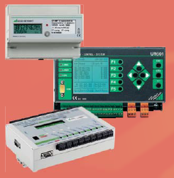
Acquisition, analysis and optimising of the energy consumption and its allocation to generating costcentresis one of the central tasks of any company. To perceive the same on every level, we offerdifferent product groups:
– Active power meters (calibrateable)
– Summation stations. To record meter readings centrally via pulse inputs or via LON bus.
– Peak load optimisers: To avoid power peaks the current energy requirement is determined andoptimised by direct consumer control.
– Energy Control System (ECS): The solution for energy data acquisition in the industrialenvironment. This system provides the data for cost centre allocation and the basis for consumerand load optimising.
Signal Conversion
As a link between the actual physical process and control engineering, we provide an extensiveprogram for safe isolation, conversion and amplifying of signals, also for Ex-zones. Safety has thefirst priority also at this point.
Head transmitters
Head transmitters are directly installed in the connecting head of the temperature sensor. The sensorsignal is converted into a 4..20 mA signal, HART signal or Profibus PA signal directly on site. Thehead transmitters may be freely programmed and parameterised.
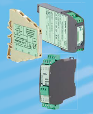 Transmitter for top-hat rail assembly Transmitter for top-hat rail assembly
Intelligent terminals in 2-wire technology are suited to the installation in subdistributor systems closeto the process or control cabinets. Their very small dimensions permit a space-saving installation.Temperature transmitters are directly assembled in the control cabinet and mainly use 4-wiretechnology. Measured variables and measuring ranges can be fully programmed which facilitatesuniveral usage and cost-saving stocks. All of our devices are galvanicly isolated, on principle, andalso available in Ex-variants.
Power supply units
Our power supply units provide 2-wire transducers with DC power and transmit the measuring signal1:1 galvanicly separated to the measuring output.
Isolation amplifiers
Active isolation amplifiers have the task of galvanicly separating input signals from output signals,amplifying them and/or converting them to another level or type of signal (current or voltage).Different Ex-variants are also available.
 Passive isolators Passive isolators
Passive DC signal isolators serve the galvanic isolation of a direct current signal which is transferredto a direct current or direct voltage signal depending on the device variant. They prevent the diversionof interference voltages and interference currents and solve earthing problems.
Application
- Peak filter
- Smoothing filter
- Actual value correction, Actual value factor
- Adaptive measured value correction
- Oscillation disabling
- Feed-forward control
- Response in event of sensor failure, sensor error manipulating factor
- Two/Three-step (action) controller
- Continuous-action controller
- Hot-runner controllers
- Fixed value control
- Follow-up control
- Ratio control
- Differential control
- Cascade control
- Program control
- Setpoint ramp
- Heating circuit/current monitoring
- pH control
 Process Management Process Management
Videographic recorders
The vidographic recorders of the LINAX A300 family are paperless recorders of the latest generation.Their modular concept facilitates the flexible adaptation to the most varied needs. Depending on thetype and design of the device users have up to 36 universal input channels at their disposal. Digitalinputs and outputs, relay outputs, Ethernet interface, RS485 (Modbus) interface as well as transducerpower supply are additional properties of the LINAX vidoegraphic recorders.
Temperature control systems
The goal of any control is to correct the change of the setpoint and the influence of interferingvariables without overshooting and swinging. However, this is only possible if the controller behavesdynamically and is adjusted to the time behaviour of the controlling system. Our controllers andcontroller systems are the professional tool for optimum and high-quality control.A specially developed PDPI control action and optimising procedure corrects changes withoutovershooting and swinging. The integrated data loggers and histories register all relevant controlprocess data in real time thus facilitating a detailed analysis of interferences. User-friendly softwaretools for commissioning (configuration, parameterising), remote diagnosis and remote maintenancesupport and simplify all relevant tasks. Our controller program comprises compact controllers, controlmodules for Simatic platforms, OEM control modules, software controllers (control algorithm) andmodular temperature control systems.
| |
|
|
|
|
|
| Features |
LINAX A303 |
LINAX A305 |
LINAX A310 |
LINAX A325 |
LINAX A330 |
| Display |
120 mm (4,7 Zoll)
LCD |
144 mm (5,7 Zoll) TFT;
120 mm (4,7 Zoll)
monochrom |
125 mm (5 Zoll) LCD |
178 mm (7 Zoll) TFT |
310 mm (12,1 Zoll) TFT |
| Front panel and depth |
144 x 144 x 171 mm |
144 x 144 x 50 mm |
144 x 144 x 195 mm |
190 x 144 x 158 mm |
288 x 288 x 195 mm |
Universal
analog inputs |
3 resp. 6 |
1, 2, 3 resp. 4
(8 via Modbus) |
6 resp. 12 |
4, 8, 12, 16 resp. 20
(40 via odbus or
Profi bus)* |
6, 12, 18, 24, 30
resp. 36 |
Memory
internal/external |
2 MB / CF card |
8 MB / SD card |
1 MB / CF card |
256 MB / SD card
or USB stick |
8 MB / CF card |
Transmitter
power supply |
24 V / 250 mA |
2 x 24 V / 22 mA |
6 x 24 V / 45 mA |
24 V / 200 mA |
5 x 24 V / 45 mA |
| Digital inputs |
3 |
via analog inputs |
6, 12 resp. 18 |
6 resp. 14 |
6, 12, 18 resp. 24 |
| Limit values / Relays |
14 / 4 |
32 / 3 |
24 / 6, 12 bzw. 18 |
100 / 6 bzw. 12 |
144/6, 12, 18 bzw. 24 |
| Interfaces |
USB,
RS232 / RS485,
Ethernet TCP/IP,
Webserver |
Ethernet:
TCP/IP, HTTP,
FTP (Server),
Modbus TCP
(Slave/Master),
Webserver,
E-Mail |
Ethernet:
TCP/IP, HTTP,
FTP (Server),
Modbus TCP
(Slave/Master),
Webserver, E-Mail,
RS485:
Modbus RTU
(Slave/Master) |
USB,
RS232 / RS485,
Modbus RTU/TCP,
Profi bus DP,
Ethernet,
Webserver, E-Mail |
Ethernet:
TCP/IP, HTTP,
FTP(Server),
Modbus TCP
(Slave/Master),
Webserver, E-Mail,
RS 485:
Modbus RTU
(Slave/Master) |
| Additional functions |
Mathematic |
Mathematic |
Batch |
Mathematic / waste
water / telealarm /
batch |
Mathematic / batch |
| Process groups |
1 |
2 |
2 |
10 |
6 |
|